Engineered from the fuel cycle up
A compact pressurized reactor designed for co-location with data center campuses. AI-controlled output adjustment, passive safety architecture, and a fuel cycle measured in years rather than months.
A complete generation system in a compact footprint
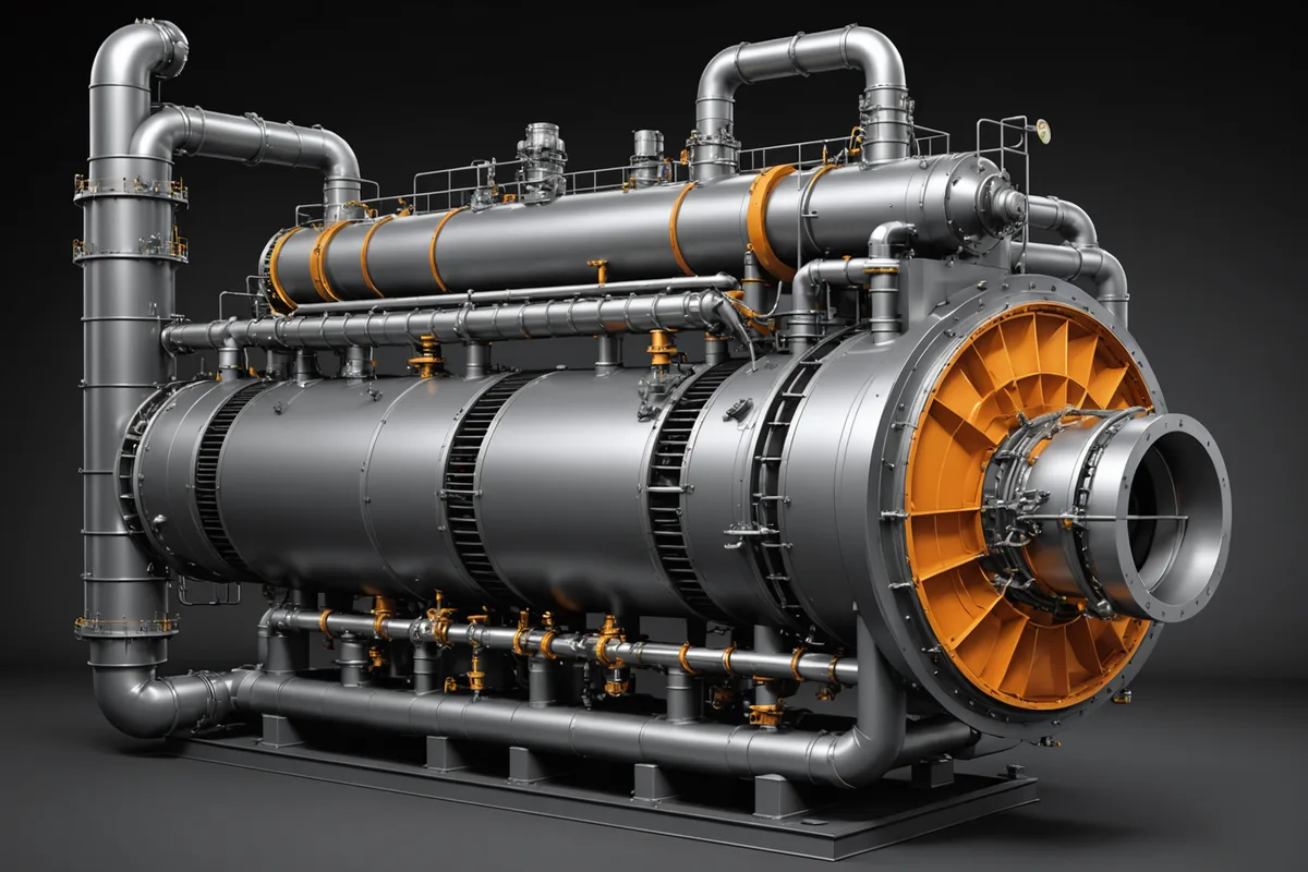
The Applied Atomics unit integrates four subsystems on a single foundation: the reactor pressure vessel and containment structure, a primary-to-secondary heat exchanger, a compact turbine-generator package, and the AI control layer that monitors and adjusts output in real time. The full installation fits within the footprint of a conventional industrial building.
Unlike grid-scale nuclear plants designed for continuous maximum output, our architecture is built around load-following. The AI control system communicates directly with your data center's power management software to align reactor output with computational demand, reducing waste and improving economics over the lifetime of the contract.
The control layer that makes load-following possible
Standard reactor control responds slowly because it was designed for manual operation at fixed output. Our AI layer replaces that with continuous sensor-driven forecasting and autonomous output adjustment, targeting a dispatch response inside five minutes.
Sensor Ingestion
Over 400 real-time sensor feeds: coolant temperature, neutron flux, turbine speed, and data center load telemetry from your DCIM system. Sampled at 100ms intervals.
Load Forecasting
A prediction model trained on power demand patterns from compute workloads generates a rolling 30-minute output forecast. Xenon transient dynamics are accounted for in the planning horizon.
Output Adjustment
Control rod positioning and coolant flow adjustments are issued automatically within safety bounds. The human operator retains override authority at all times, with full audit logging of every automated action.
Low-enriched uranium with a multi-year fuel cycle
The design uses low-enriched uranium dioxide fuel in a standard ceramic pellet form compatible with established supply chains. Fuel cycle length is targeted at four to six years per loading, reducing operational disruption and outage frequency compared to large-scale plants refueled annually.
Spent fuel volume per unit is a fraction of what a utility-scale plant produces. Design targets for annual spent fuel output are in the single-digit cubic-meter range, stored on-site in passive dry casks under standard NRC protocols. We describe these as design targets, not as values verified through operational experience.
Read: Waste volumes for compact fission units4-6 yr
Target fuel cycle length per loading
<5 m³
Design target: spent fuel volume per unit-year
LEU
Low-enriched uranium dioxide ceramic pellet fuel
Passive safety features that work without operator action
The design philosophy prioritizes passive safety: systems that respond to physical laws rather than instrumented commands. In the event of a loss-of-coolant scenario, the reactor reaches subcritical condition through inherent negative temperature feedback without requiring active injection or operator response.
Negative Temperature Coefficient
As coolant temperature rises above design range, the reactor naturally reduces reactivity. The physics of the fuel lattice provides the first line of protection without any active system.
Passive Decay Heat Removal
Residual decay heat after shutdown is removed by natural circulation through a separate loop connected to an elevated heat sink. No pumps or external power required for the critical cooling period.
Compact Containment
The low power density of the compact design reduces containment size requirements. The entire primary system is enclosed within a cylindrical steel-reinforced concrete structure designed to retain integrity under postulated accident scenarios.
Defense-in-Depth Barriers
Four independent barriers separate the fuel from the environment: the fuel matrix, the fuel cladding, the reactor coolant pressure boundary, and the containment structure. No claimed certification, described as design intent.
Navigating NRC advanced reactor licensing
We are preparing initial design documentation for the NRC Part 53 licensing pathway, the framework established for advanced non-light-water and small modular reactor designs. Our regulatory team, led by a specialist in advanced reactor licensing, is building the probabilistic risk assessment and safety analysis report required for a pre-application engagement with the NRC.
We are honest about where we are: pre-license, pre-construction, working through the front-end engineering and regulatory preparation phase. Our partners and investors work with us on a multi-year horizon. First power is a milestone we plan for, not one we claim to have reached.
Read: NRC advanced reactor licensing pathwaysLicensing Phase Status
Current
Pre-Application Preparation
Preparing design documentation and probabilistic risk assessment for NRC pre-application engagement under Part 53.
Phase 2
Pre-Application Meeting
NRC staff review of design concept and identification of key review areas prior to formal license application submission.
Phase 3
License Application
Formal application submission followed by NRC safety and environmental review period, targeting first-power within the planning horizon of current design partner discussions.
Talk to our engineering team
We discuss the technical architecture in detail with prospective design partners. If you are evaluating on-site generation options, we can walk through the full system design.
Start a Conversation